Review parts list
Review options
Order parts
Configure PCBs for selected options
Soldier parts to PCBs
Initial assembly (connect PCB's)
Initial testing
Install Horizontal Compass
Test Horizontal Compass
Install optional devices
Test optional devices
Load operational software
Install PowerTroll in case (Build Case)
Put into Service
I occasionally have kits, but not at the moment. In any event most of the parts are readily available directly from my sources so the only reason you'd buy them from me would be convenience. I don't buy in large enough quantity to get a real break, and I have to make up my expenses in packaging, etc. In short I'm not the cheapest place for you to get those parts.
The place I can save you some money is the PCBs. I usually have some available for $25 per set.
Sometimes part numbers change. I try to keep up, modifying this page and the parts list to keep them in sync. If you order parts then later try to follow these instructions it is possible for some confusion to creep in 'cause your part # is old and the instructions refer to new number, so be careful. I usually show the part I'm talking about so do the eyeball test! BTW, it's usually Jameco part numbers that change, mostly to accommodate new ROHS compliant parts. If the part number I reference is not found, try searching Jameco for the text of the part name instead of the part number.
Part prices are also subject to change. I do not attempt to keep those
current.
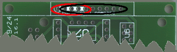
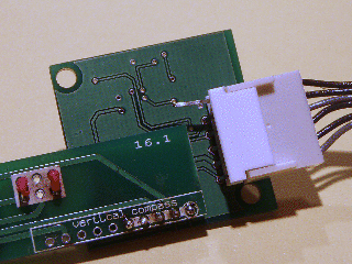
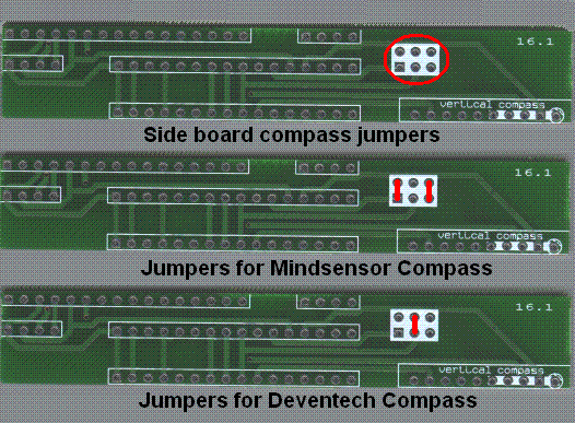
The small PCB (Figure 1 below, with 3 images) has a single jumper area (white on the PCB, circled in red in the top image of Figure 1) to select what kind of vertical compass you will install.
If you will not install a vertical compass you do not need to install any jumpers.
If you will install a Mindscape compass, install two jumpers as indicated in the middle image of Figure 1.
If you will install a Devantech compass, install one jumper as indicated in the bottom image of Figure 1.
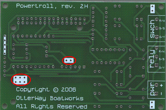
The large PCB (Figure 2 below) has 2 jumper areas (white on the PCB,
circled in red below) on its back (opposite side from where most parts are
installed). The larger of these jumper areas, with 6 holes, is like the jumper area on
the small PCB in Figure 1. It is used to select what kind of horizontal compass you
will install. Every PowerTroll will have a horizontal compass, so you must
install one of the following two jumper configurations. If you will install a Mindscape compass install two jumpers as indicated in
the middle image of Figure 1. If you will install a Devantech compass install one jumper as indicated in
the bottom image of Figure 1. The smaller of large PCB jumper areas, with 2 holes, is used to configure
the accelerometer. If you will not install an accelerometer
install a jumper between these 2 holes.
Solder the Four reed relays
Solder the Resister pack
Solder the Switch
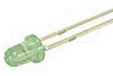
Solder a Red led
Solder a Green led
Solder the large 4pdt relay
Solder two of the 3 contact connecters Solder a 2 contact connecter Solder the 3.3v voltage regulator
Solder two
This completes the assembly of the main PCB (with the
exception of the horizontal compass and optional accelerometer and FPU, but
those installations will be covered later).
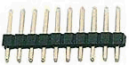
Jameco
103392 into three parts: Two 4 pins
fragments and a 2 pin fragment. Discard the 2 pin fragment.

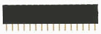
Jameco 308592 into the front of the PCB in the locations shown below, as
nearly perpendicular to the PCB as possible. Direction is
not significant.

This completes the side PCB (unless you will install a vertical compass,
but that installation will be covered later).
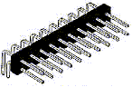
Jameco 204020 into the front of the PCB in the locations shown
in Figure 5 below. Note the part has 32 pins, not 20 as shown above. The shorter ends of the pin
(on the side with the right angle bend) should be the soldered in
with the longer ends pointing toward the edge of the PCB (toward and
overlapping the 1098/16/0/0 text on the PCB) and as nearly parallel to the
PCB as possible.
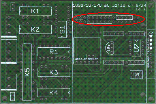
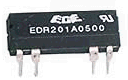
Jameco 106472 into the PCB in the locations noted as K1, K2, K3, and K4 in Figure 5
above. Note that K1, K2, and K3 have their pin 1 on the left side above, but
K4 is oriented with pin 1 to the right.
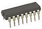
Jameco 108628 into the PCB in the location noted as R1 in Figure 5 above.
Note that R1 has it's pin 1 to the right.
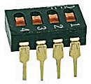
Jameco
139002 into the PCB in the location noted as S1 in Figure 5 above. Note that
S1 has it's pin 1 down. Also note the additional 8 holes behind/above S1.
These are to allow 6 or 8 position switches (such as Jameco 139012 supplied
with some of my 'kits') to be installed in the S1
location. If you are installing such a switch make sure your switch is
installed with pin 1 down and any unused PCB holes are at the top!
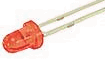
Jameco
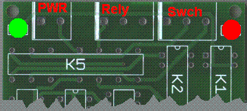
333171 into the PCB in the location noted with the RED dot in Figure 6
below. Pin 1 (the longer lead) is to the left Figure 6.
Jameco
175679 into the PCB in the location noted with the GREEN dot in Figure 6
below. Pin 1 (the longer lead) is to the left Figure 6.
Jameco
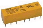
206543 into the PCB in the location noted as K5 in Figure 6 above. You will
note this part is asymmetric and will only fit into the PCB in one direction.
Jameco
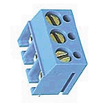
153355 into the PCB in the locations noted as 'Swch' and 'Rely' in Figure 6
above. Note the side holes (left side in above part picture) must face the
edge of the PCB, not the center of the PCB.
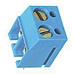
Jameco
152347 into the PCB in the location noted as 'PWR' in Figure 6 above. Note
the side holes (left side in above part picture) must face the edge of the
PCB, not the center of the PCB.
(Mouser 511-L78L33ACZ)
into the PCB in the location U5 (between the two red ellipses) in figure 7
below. Be sure the flat portion of the regulator is positioned pointing away
from the relays as shown on the PCB. Leave about 0.25 inches of wire between
the plastic of the voltage regulator and the PCB when soldering. After the
solder has cooled bend the part over (away from the relays) so that the flat
portion of the voltage regulator is close to the PCB.
Jameco
103392's into the PCB into the locations shown by the red ellipses in figure
7 below. The shorter ends of the pins should be the soldered in with the
taller ends as nearly perpendicular to the PCB as possible.
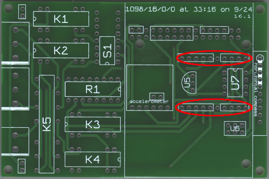
Figure 7
Before soldering in the compasses and other expensive components it is worthwhile doing some early testing to ensure power is flowing, relays work, etc. To do so it is necessary to connect some of the PCB's, apply power, attach a serial interface, and other steps which will be undone when the testing is completed - then redone in final assembly.
Install the Acroname Moto board by pressing it onto the pins in the locations shown by the red ellipses in figure 7 above. The Moto's 'notch' and red/green led's should be on the part of the Moto that overhangs the end of the PCB.
Install the side PCB by pressing it onto the pins in the location shown by the red ellipse in figure 5 above and at the same time onto the Moto board pins above the figure 5 pins.
6 volt power needs to be applied to the 2 contact connector installed in the location noted as 'PWR' in Figure 6 above. The connection closest to the Green LED is ground as noted on the silkscreen on the back of the PCB. This is most easily accomplished by by installing the radioshack 273-1742 adaptaplug with its all black wire next to the Green LED. Then connect the adaptaplug to the radioshack 273-1859 6 volt adapter. When instructed to power on the device plug the other end of the 6 volt adapter into a standard auto 'cigarette ligher' 12 volt source.
Build and install the cal-term connecters
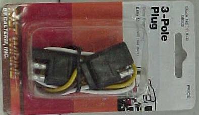
Cut a Cal-Term 08002

Figure 8
in half so that you have two ends each with about 6 inches of all three (yellow, brown, white) wires.
Remove 1/4 inch of insulation from the ends of all 6 wires and 'tin' the exposed wire with your soldering iron.
One of the connectors will have one exposed pin and two shrouded pins, like the right connector in Figure 8 above. This is the connector going to the Electro-Steer relays. With the PCB positioned as shown in Figure 6 above, connect the white, brown, and yellow wires respectively to the right most, center, and left most pins of the part installed in the location shown as 'Rely' in Figure 6.
The other connector will have two exposed pins and one shrouded pin, like the left connector in Figure 8 above. This is the connector going to the Electro-Steer switches. With the PCB positioned as shown in Figure 6 above, connect the white, brown, and yellow wires respectively to the right most, center, and left most pins of the part installed in the location shown as 'Swch' in Figure 6.
Power Off test - have power on to your electro-steer, but off to the powertroll PCB's (ie, the 12v adapter not plugged in).
Make sure your Electro-Steer works and note which way it moves when you press it's UP and DN buttons.
Disconnect your electro-steer relays from the electro-steer switches.
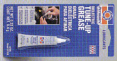
Put a little dielectric grease
on the exposed pins and
inside the shrouded pins of all the plugs - Electro-Steer and PowerTroll.
This will make connecting and disconnecting them much easier, and long term
provides some protection from moisture and corrosion.
Plug your electro-steer switches into the "two exposed pins" connector on the PowerTroll PCB. Plug your electro-Steer relays into the "one exposed pin" connector on the PowerTroll PCB.
Check to make sure your Electro-Steer works as it did before. Does it move the same direction it used to when you press UP? when you press DN? If not something is wrong and you must find and fix it before going any further. But if your Electro-Steer does work as it did before your PowerTroll has passed it's Power Off test.
Power On test 1
Unplug your Electro-Steer switches and relays from the PowerTroll PCB.
Plug in the 12v adapter (thus applying power to the PCBs).
If you listen carefully you may hear the PCB relays click when you plug it in
You may also observe the the green led on the Moto board (not the one you installed on the large PCB) flash rapidly for about a second then turn off.
You should observe the red led on the Moto board (not the one you installed on the large PCB) light up and stay lit. If you observe this and nothings smells funny (like fried wiring) your PowerTroll has passed it's 1st Power On test.
Unplug the 12v adapter (thus removing power from the PCBs).
Power On test 2
Plug your Electro-Steer switches and relays back into the PowerTroll PCB.
Check to make sure your Electro-Steer works as it did before. Does it move the same direction it used to when you press UP? when you press DN? If not something is wrong.
Plug in the 12v adapter (thus applying power to the PCBs).
Check to see if your Electro-Steer works as it did before. It should not. The switches should be dead, and the Electro-Steer should not move at all.
Unplug the 12v adapter (thus removing power from the PCBs).
Check to make sure your Electro-Steer works as it did before. Does it move the same direction it used to when you press UP? when you press DN? If so your PowerTroll has passed it's 2nd Power On test.
Power On test 3
A serial adapter needs to be attached to load and run test software on the Moto board. Connect an acroname C10-SER-INT-CONN-EXT cable to the pins of the left serial connection shown in figure 3. The leftmost pin is pin 1, so the yellow wire should be on the right. Connect the other end of the cable to an acroname S13-SERIAL-INT-CONN Serial Interface connector. You'll note one side of the SERIAL-INT-CONN has components mounted on it, and the word "brainstem" accros the end the cable plugs in. Make sure the yellow wire is on the end of the "m" in "brainstem". Connect the db9 connection to a serial cable attached to a serial port on your computer. Know the name of the serial port (COM1, COM2, etc).
Download and install the Acroname brainstem SDK onto your PC. This will be used to load test programs and observe results. Configure the Console program for the serial port and learn to use the 'console' program to compile and test simple TEA programs as described in Acroname's documentation.
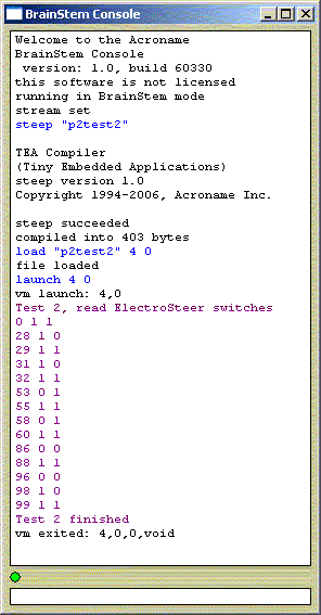
Download p2test2 (program to Read & print the ElectroSteer switches). Compile the program ('steep "p2test2" '), load it to the Moto ('load "p2test2" 4 0'), and run it ('launch 4 0'). As described in the source of p2test2, it loops reading the state of the Electro-Steer switches and prints what it finds. So while it runs you should press the UP and DN switches and observe the changes. Figure 9 is a sample of what your run should look like:

Figure 9
Examining the output (starting under 'Test 2, read ...') note each line is 3 numbers. The first is the loop count (which 1/10 of a second), the second is the UP switch (1 when un-pressed, 0 when pressed), the third is the DN switch, and only changes are printed. So reading the above, the switches were both unpressed, then ~ 3 seconds (28/10th) later I pressed the up switch and a 1/10 second later let it back up, ... Notice at ~ 9 seconds in (86/10) I pressed both switches at once.
Of course while you are doing this your Electro-Steer does nothing - because this program does not tell it to.
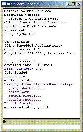
Download p2test3 (Drive the ElectroSteer relays). Compile the program, load it to the Moto, and run it. As described in the source of p2test3, it drives your Electro-Steer back and forth to demonstate it can do so. Figure 10 is a sample of what your run should look like:

Figure 10
When it says "going starboard" the red led on the PCB should light up and your Electro-Steer should slew one direction. When it says "going port" the green led on the PCB should light up and your Electro-Steer should slew the other direction. For the single and double "rattles" both leds should flash and your Electro-Steer should make noise but not make any net movement (it will move slightly one way then back).
When this test fails it's usually because one (or both) leds are installed backwards...
If you fooled with the Electro-Steer switches while this ran you discovered they did nothing - because this program does not read or act on them.
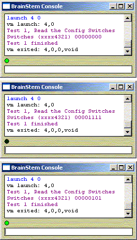
Download p2test1 (Read & print the config switches). Compile the program, load it to the Moto, and run it. As described in the source of p2test2, it reads the PCB switches and prints their state. You should run this test several times; once with all four switches ON, once with all four OFF, and at least once with alternating ON, OFF, ON, OFF. Figure 11 is a sample of what your runs should look like:

Figure 11
This test pays no attention to the Electro-Steer switches or relays so they are both inactive.
When these test all run as indicated your PowerTroll has passed it's 3rd Power On test.
With the PCB positioned as shown in Figure 6 above, put a dot of red fingernail polish on the PCB end of the three wires you installed into the connector in the location shown as 'Rely' in Figure 6. Also put a dot of red fingernail polish on the plug attached to the other end of those wires (with one exposed pin and two shrouded pins, like the right plug in Figure 8 above). Allow this fingernail polish to dry hard before proceeding. This marking will be used later when you install the PCB into a case.
Jameco
103392 into two 5 pins
fragments. Save one 5 pin fragment for installation of a Mindsensor vertical
compass.
Figure 12
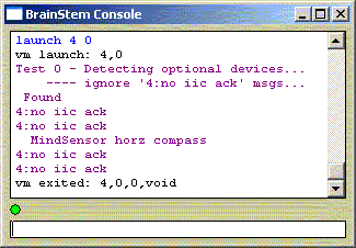
Download p2test0 (Detect & report installed devices). Compile the program, load it to the Moto, and run it. As described in the source of p2test0, it determines what devices are installed on the PCB and prints the results. Figure 13 are samples of what your run might look like. Ensure that a horizontal (not vertical) compass is reported!

Figure 13
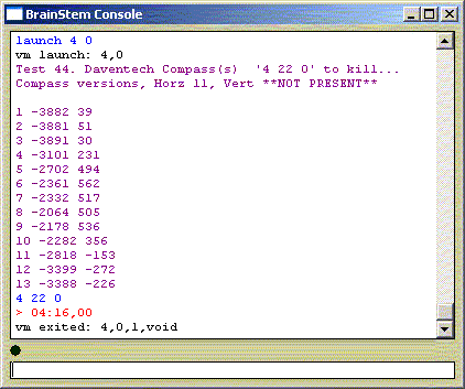
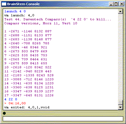
If you installed (and p2test0 reported) a Devantech compass then download p2test4 (Read & print the Devantech compass info). Compile the program, load it to the Moto, and run it. As described in the source of p2test4, it prints the version information for all Devantech compasses and then loops printing heading x and y information from the compass(s). You should cancel the program when you have seen enough. To cancel the program type '4 22 0'. Figure 14 is a sample of what your run might look like.

Figure 14
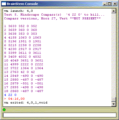
If you installed (and p2test0 reported) a Mindsensor compass then download p2test5 (Read & print the Mindsensor compass info). Compile the program, load it to the Moto, and run it. As described in the source of p2test5, it prints the version information for all Mindsensor compasses and then loops printing heading x and y information from the compass(s). You should cancel the program when you have seen enough. To cancel the program type '4 22 0'. Figure 15 is a sample of what your run might look like.

Figure 15
Unless you are installing optional devices (accelerometer, FPU, vertical compass, wireless interface), when the preceding test all run as indicated your PowerTroll is ready to be loaded with operational software, installed in a case and put into service.
Accelerometer
Jameco
103392 into a 6 pin fragment and a 4 pin fragment. Discard the 4 pin
fragment.FPU
Solder the FPU into the location marked U7 in Figure 7 above (between the red ellipses). In that figure the FPU's pin 1 is the upper left pin. Pin 1 on the chip is identified by the black dot. Be careful soldering this chip as it is more sensitive to heat and static than most other PowerTroll parts.
Vertical Compass
Mindsensor
Firmware: Mindsensor compasses come standard with an I2C address of E0, and with firmware before v27 do not correctly report 'raw' heading information as necessary for tilt compensated operation. But the vendor will supply you with firmware upgrades to address both issues.
If you ask, he will sell you compasses pre-configured with firmware v27 (+) and will program one of them with address E8 (which is what PowerTroll expects for the vertical compass).
If you already have a couple of these compasses you can readily program them yourself. Get E0 and E8 firmware (at least v27) from Mindsensor, then install it to your horizontal and vertical compasses (respectively) with WinPic, and a programmer and adapter. Both vertical and horizontal compasses can be (re)programmed after being installed on the PowerTroll PCB's. Below, views of the back of a compass with the adapter and programmer pressed into place for programming...
Note one of the pins on the adapter is bent up, not being plugged into the compass. This is required...
Jameco 103392 left over
from your installation of a Mindsensor horizontal
compass. Find it.
Figure 16
Devantech
Wireless interface
Note - the wireless interface (top ellipse in Figure 4)and the standard serial interface (left ellipse in Figure 3) are wired in parallel to the Moto serial port. They should not both be plugged in at the same time!
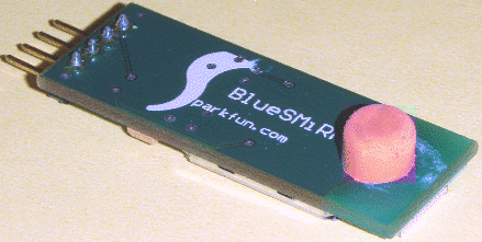
Superglue about 3/16" of pencil eraser to the bottom of the smirf (wireless interface) as shown below:

Smirfs come in 4 pin and 6 pin varieties. Referring to the side PCB in Figure 4, install a 6 pin smirf eraser down (toward the relays) in the left most holes of the topmost of the three recepticles circled in red. If you have a 4 pin smirf it goes in the same place, offset by one hole. So a 6 pin smirf would be in holes 1-6, a 4 pin smirf goes in holes 2-5. It is not necessary to modify the 6 pin smirf to tie pins 1 and 6 together; that circuit is already in place on the side PCB.
Accelerometer
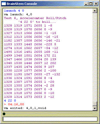
Download p2test6 (accelerometer roll and pitch). Compile the program, load it to the Moto, and run it. As described in the source of p2test6, it loops reading the accelerometer and displaying roll and pitch You should cancel the program when you have seen enough. To cancel the program type '4 22 0'. Figure 17 is a sample of what your run should look like:
Figure 17
FPU
Download and install the FPU ide from the micromega web site.
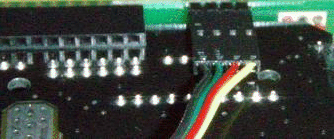
Apply power to the moto board and attach a serial interface to the FPU serial port (referencing Figure 3, the pins you installed in the rightmost of the two red ellipses). As below, the yellow wire on the interface cable should be to the right.
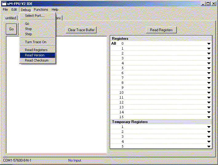
Start the FPU ide and select the Debug tab, then select 'Read Version' from the Debug menu as shown below
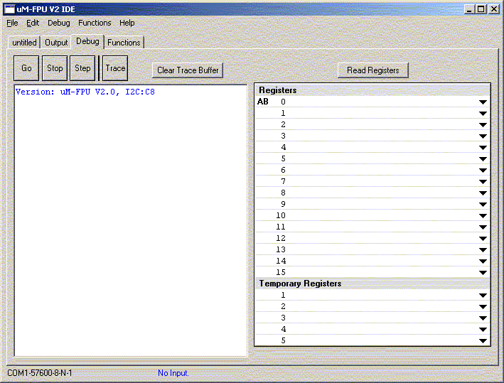
The FPU version should display as shown below

Vertical Compass
Testing of the vertical compass is identical to testing the horizontal compass (discussed above) except than when you have a vertical compass the test programs report it and display test results for it as well as for the horizontal compass. Note in Figures 14 and 15 above the vertical compass version number (vert) is '**NOT PRESENT**', but that in Figures 14b and 15b below version numbers are shown!

Figure 14b
Wireless interface
The best way to test the wireless interface is to power up the Moto, then open the Prefs application on your Palmpilot and tap 'Bluetooth' (under 'Communications'). Make sure Bluetooth is turned ON. Then tap 'Setup Devices', then 'Trusted Devices', then 'Add Device'. Make sure the 'Show' popup menu at the top of the form is set to 'All Known Devices'. The smirf should show up as either 'BlueRadios' (it's generic name), or 'PowerTroll_NNNNN' where NNNNN is the PowerTroll serial number. Tap 'cancel' to get out of the Add Device context (the PowerTroll does not need to be a 'trusted device').
Installing the operational software consists of downloading it, transferring the Moto part to the Moto, transferring the FPU part to the FPU (if you have an FPU installed), and setting the serial number (that came with the PCBs) into eeprom.
Download the steer10 operational software and UnZip it to your aUser directory. You'll get two files: steer10.bag, and steer10-heading.fpu.
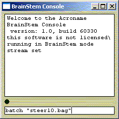
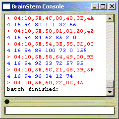
Transfer the Moto part software to the Moto by typing 'batch "steer10.bag"' in the console, as shown below (left). Note that this may require 60-90 seconds to finish, and nothing happens during that time. Be sure to wait at least 3 minutes before you give up and decide it did not work. When it is done the console will fill with 'junk' as below right.
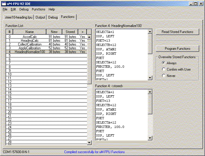
Transfer the FPU part using the FPU ide installed above under "Test optional devices". Start the FPU ide. Select 'Clear Functions' from the Functions menu. Then select 'Open' from the File menu and open "steer10-heading.fpu" (from the zip file). Then select the tab that used to say "untitled" but now says "Steer10-heading.fpu" and click the 'Compile' button on the form. Select 'Program Functions' from the Functions menu. Finally select the Functions tab and ensure it looks alot like this:

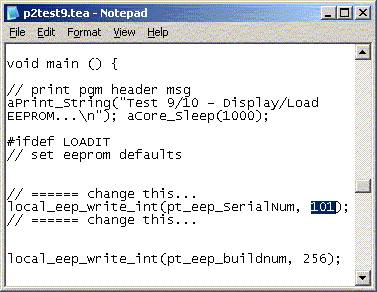
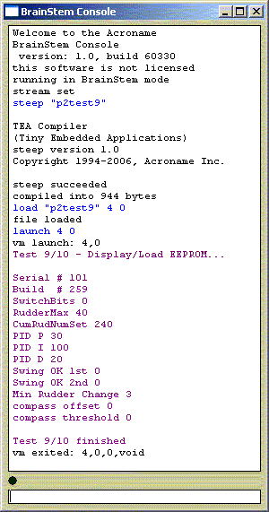
Set the serial number that came with the PCBs into eeprom by appropriately modifying p2test9 then compiling and running p2test10 (which 'includes' p2test9). Note a variety of parameters are settable using p2test9/10, see the eeprom page for information about all of them. Below (left) using NotePad to set a serial number in p2test9; (right) compile, load, and run p2test10.

The purpose of a case for the PowerTroll is to protect it from physical and environmental hazards aboard your boat. It should protect the electronics from drops, kicks, stuff dumped on top of it, and other physical abuse. It should keep the electronics dry. It should isolate the wiring from push-pull type stresses. It must not be magnetically active (no metal boxes).
OtterBox and Pelican boxes are both strong, attractive, waterproof and non-metallic. I think the instructions to follow apply about equally to either and to other brand-x boxes like them. Which? Personal choice, I think the Pelican looks better, but I think the Otterbox is tougher.
Sizing: a Pelican 1040 (smallish) or Otterbox 3500 (largish) work great.
Access: You will need to drill one 3/8 " hole in the side of the box. All the wiring goes through this hole, and it ends up being the most likely place for water to get into a previously waterproof box.
Foam: You should get one of the boxes that includes pick-pluck foam. That means a colored top as the clear top boxes come without foam. I have used a clear top box with other foam but there isn't much reason to go to that trouble.
The rest of the instructions are specific to an OtterBox 3500 with foam and also work for a Pelican 1040, but you should be able to 'follow along' even if you use something else.
Both boxes have sides I will refer to Up and Down because I picture the box sitting on the Down side with the Up side up. In that position there are four more sides between Up and Down: One has hinges (I call it Left), there are clasps opposite the hinges (I call this side Right), there is a strap attachment on one of the sides between the hinges and the clasps (I call this side Top), and a 'clean' side opposite the strap attachment (I call this side Bottom).
Remove the foam and any other removable lining from the case. Drill the 3/8" hole near the bottom of the Bottom side (not the Down side!). It will be easiest if you start with a small hole (1/8") then go larger (1/4") and finally finish with the full sized 3/8" drill.
It's likely
the remaining box lining stuck to the drill and was ripped out while you drilled the
hole, if so press it back inside the box. If it's loose enough that you
think it might fall out you can glue it in using a little ShoeGoo
.
Obtain a 1 inch length of 3/8" heat shrink tubing and a 3/8" grommet. Using a razor or X-Acto knife cut the grommet in half so that you separate the part that would be on the outside and the part that would be on the inside, thus allowing the grommet to be installed in a thicker media than intended.
Referring to Figure 6, remove the wiring attached to the PCB at locations marked PWR, Rely, and Swch.
Put the 3/8" heat shrink over the PWR, Rely, and Swch plug wiring, leaving about 1 inch between the connectors and the heat shrink. Put one of the grommet halves onto the wiring, with it's cut side facing away from the plugs, but pushed back past the heat shrink all the way to the plugs. Fill the excess space inside the heat shrink with ShoeGoo (use a tooth pick to pack it). Use a heat gun to shrink the heat shrink tubing and observe some of the ShoeGoo being squeezed out. Don't try to wipe it off, just leave it. Put the completed wiring assembly on some newspaper (to catch ShoeGoo drips) and let it 'harden' a few days. After it's hardened trim off objectionable ShoeGoo (but don't get too aggressive).
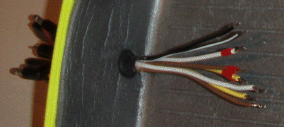
Put the wiring assembly in the 3/8" hole you drilled thru the box, with the plugs (and grommet half) on the outside. With the heat shrink part about 1/2 in and 1/2 out, slide the grommet half up the the case. Now slide the other grommet half onto the wiring from the inside of the case. Pack the area between the two grommets with ShoeGoo and push the grommets together. Put the combined box and wiring assembly on some newspaper (to catch ShoeGoo drips) and let it 'harden' a few days. After it's hardened trim off objectionable ShoeGoo (but don't get too aggressive). Below, a picture of a case with wiring assembly:

I've made a handful of these and each has been 'waterproof' to my requirements (keeps the rain and other spilled stuff out). I tested one by putting it in a bucket of water for 5 minutes; it came up dry. If your requirements are more stringent than mine I suggest you devise better tests to be sure your case meets those requirements and will continue to meet them.
Paint or decals can be applied to the case for a finishing touch. Here are some images I printed on decal paper and applied with good results. The yellow background is a close match to a 'yellow' pelican case (at least it was when it came off my printer). I had expected decals to be problematic in a wet environment but my experience has been that after setting a few weeks even a lot of water will no longer loosen them at all!
With the case completed all that remains is to install the assembled PCB's inside the case. Place a bottom 1/4"-1/2" layer of pick-pluck foam in the case. Lay the main PCB on the foam, component side up, with the blue connectors toward the case wiring. Connect the wiring:
Two of the wires are of lighter gauge than the other 6 wires. One of these two wires is black, the other is "black with a white strip". Connect these wires to the 2 contact connector installed in the location noted as 'PWR' in Figure 6 above. The side closest to the Green LED is ground as noted on the silkscreen on the back of the PCB, so connect the black wire to that side.
One set of white, brown, and yellow wires will have dots of red fingernail polish. With the PCB positioned as shown in Figure 6 above, connect these white, brown, and yellow wires respectively to the right most, center, and left most pins of the part installed in the location shown as 'Rely' in Figure 6.
The other set of white, brown, and yellow wires will not have dots of red fingernail polish. With the PCB positioned as shown in Figure 6 above, connect these white, brown, and yellow wires respectively to the right most, center, and left most pins of the part installed in the location shown as 'Swch' in Figure 6.
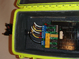
Below a picture of an open case with the PCB's and wiring installed.

Finally form a block of pick-pluck foam to go on top the PCB's. The idea is
the PCB's will be gently cushioned within the box by the top and bottom
foam. Actually, I have found it easier to make several smaller 'top' blocks
rather than one large one, but that's really up to you.
Set the configuration switches. Referring to Figure 5, the DIP switch installed in location S1 has 4 switches, starting with #1 closest to the center of the PCB and ending with #4 closest to the edge of the PCB. It may be that S1 has more than 4 switches, but if so only the inner-most 4 are actually connected to anything. These are 'soft' switches, meaning they do nothing other than communicate their state to the software. Software associates the state of the switches to some action. My operational software (see 12 above) associates the following actions with the 4 switches:
| Switch | Off (On) Note ON has switch toward "blue connectors" on PCB |
| 1 (closest to center of PCB) | Fwd (Rev); ie, which relay makes boat go starboard/port? |
| 2 | Console (Palmpilot); ie, output is to console pgm or to Palmpilot app? |
| 3 | Hold heading (Calibrate); ie, hold heading or process calibration info? |
| 4 (closest to edge of PCB) | 3D (2D); ie, use tilt comp if hardware available (Use only horizontal compass) |
These should all be Off.
Review and update EEProm
configuration parameters as necessary.
Find a place for the PowerTroll. It needs to be located in a place where you have easy access (to hook up cables, etc) but it will not be bumped, jarred or moved around in operation. Bumping and jarring will effect the accelerometer, and being moved around may change the alignment between the boat and the compass, causing a perceived change in heading, which the PowerTroll will try to correct.
The PowerTroll needs to be placed right side up and as horizontal as possible. Being upside down will cause it to steer in the wrong direction. Being mounted at an angle will seriously reduce the compass accuracy - even if you are using a tilt compensated compass.
Make sure all your cables (including the 12v adapter) are long enough to go from your selected location to wherever they are needed.
Connect the PowerTroll cables to the Electro-Steer relays and switches, using an extension cord if necessary. You should use some dielectric grease on the plugs. This tends to exclude moisture and makes it much easier to plug/unplug the cables. Make sure you have ready access to the places where the cables connect so that you can change them if necessary.
Test the Electro-Steer one last time with PowerTroll unpowered. Test the Electro-Steer with PowerTroll powered and in manual mode. Test the Electro-Steer with PowerTroll in automatic mode.
Proceed to the Operation page for initial calibration...