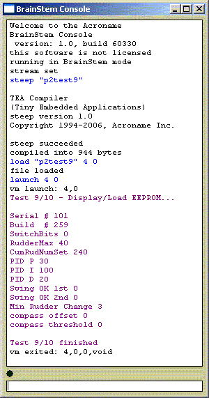
PowerTroll control parameters are persisted to eeprom on the Moto board - actually at the top of program slot 2 (immediately under slot 3).
In the discussion that follows I speak of 'rudder' - which you should interpret to mean the position of the trolling motor as it moves in 1/10 second increments of the Electro-Steer steering. The following table describes each parameter:
| Parameter Name | Parameter Discussion |
| SerialNum | Assigned PowerTroll serial number (comes with
your PCBs). Used to prevent wireless remote from accessing wrong PowerTroll(s)! Default is 101, valid for
wired use but not accepted by
wireless remote.
This should be entered once and p2test9/10 run to set it into eeprom. Thereafter it should not be changed by p2test9/10, so the program line in p2test9 that changes it should be commented out. |
| BuildNum | Software version loaded into Moto. Checked by
software at startup to ensure eeprom is correct for software version. If the
two do not match the software rewrites eeprom with its internal default
values. A value of 256 should be entered once and p2test9/10 run to set it into eeprom, then the operational software started to set defaults into all other values (including BuildNum. Thereafter it should not be changed by p2test9/10, so the program line in p2test9 that changes it should be commented out. |
| SwitchBits | Pseudo switches used to select PowerTroll options. See following description/table. |
| RudderMax | Time, in 1/10 seconds, for the Electro-Steer to go lock-to-lock. Default value is 40, or 4 seconds, which is what a normal Electro-Steer takes when the Lock bolts are in the outside holes. You should time your Electro-Steer and put in the closest value you can measure. If this is wrong (for example, if you left it at 40 but your Electro-Steer only takes 2.5 seconds so you should have entered 25) the PowerTroll will not be able to establish a 'center' point and will hunt endlessly over the desired course instead of holding that course. |
| CumRudNumSet | Time, in seconds, between halvings of the running average rudder position. At each halving both the sum of the rudder positions and the number summed is halved. If this is done too frequently the average will be over effected by recent changes (like getting back on heading) but if it is not done often enough the average rudder will take to long to assume a new center value after a heading change. Default value is 30 seconds. I recommend setting this to about the time it takes your boat to go all the way around when it is 'hard over' at trolling speed. |
| PID_P | Proportional control (how much rudder is applied based on how far off heading). When value is 100, one degree off heading will generate 1/10 of a second of rudder change off center (all else being equal). In a typical Electro-Steer setup that goes lock to lock in 4 seconds there are 2 seconds, or 20 1/10 of a second of steering to go 'hard over'. So being 20 degrees off heading will generate a 'hard over' steering response. If value was 200 it would only take 10 degrees off heading to do that; if value was 50 it would take 40 degrees off heading to go 'hard over'. An appropriate value depends mostly on how effective helm control is at your trolling speed. The more effective it is the lower the value should be. So of course the faster you troll the lower the value. |
| PID_I |
Integral control (what should the rudder position be when the boat is not off heading - ie - where is the rudder 'center' position?). This is a value that will change; for example your helm is different holding a heading quartering the wind as opposed to going downwind. The value is obtained using a running average of past rudder positions. There are two tuning constants: PID-I specifies how strong the tendency to 'center' will be, and CumRudNumSet defines the period of time used to obtain the average. I leave PID-I at it default value of 100 and tune PID-P and PID-D around it, so the only meaningful integral control is CumRudNumSet, which is described above. |
| PID_D | Derivative control (how much rudder is applied to counter 'swing'). When value is 100, 1 degree off swing will generate 1/10 of a second of rudder change off center (all else being equal). Note that if the boat is swinging away from the desired heading this will add to the proportional input, causing the swing to slow down, stop and go the other way. When the swing is toward the desired heading this will subtract from the proportional input, causing the swing back toward the desired heading to slow down and stop by the time the desired heading is reached. An appropriate value depends mostly on your boat's directional stability. If you boat quickly stops swinging by itself when you center the trolling motor (or kick it out of gear) then some small value (5-10) might be good. If it keeps on swinging awhile after you center the trolling motor you probably need a higher value (30-50). But also note your boat's directional stability probably depends on speed, so the faster you troll the lower the value. |
| Swing_OK_First | Degrees off heading before swinging back to heading is only half suppressed (half PID_D is used). If zero is specified (the default) then the normal value of PID_D is used regardless of how far off heading. Swing-OK-First should be between 0 and Swing-OK-Second. |
| Swing_OK_Second | Degrees off heading before swinging back to heading is completely unsuppressed (PID_D is considered to be zero). If zero is specified (the default) then the normal value of PID_D is used regardless of how far off heading. Swing-OK-Second should be zero or greater than Swing-OK-First. Swing is normally suppressed whether it is away from desired heading or back toward desired heading. Swing-OK-First and Swing-OK-Second provide a mechanism to allow some swing back toward desired heading. This can enable faster heading correction but also tends to exacerbate 'hunting' - a tendency to swing back and forth across the desired heading instead of settling on the desired heading. |
| Min_Rudder_Change | Time, in 1/10 seconds,of the minimum rudder movement allowed. A calculated rudder change of less than this amount will be suppressed. The purpose is to suppress constant meaningless corrections due to slight compass changes when the boat rocks, etc. Should be some small number (1, 2, 3). |
| Compass_Offset | Number of degrees to be added to heading to convert PowerTroll headings to actual boat headings. This is only significant if you have a way (like a wireless remote) to actually see the PowerTroll headings, in which case it is used to coordinate what PowerTroll reports as the heading and what an external compass reports. |
| Compass_Threshold | Time, in seconds, between halvings of the running average compass. Like CumRudNumSet, but for the compass instead of the rudder. Can be considered compass dampening. Dampening is most useful in coaxing useable rough water headings from a 2d (not tilt compensated) compass. If zero is specified (the default) then no running average is used, instead compass headings over one second are averaged and used at the end of that second to determine boat heading. If set non-zero a running average is used over the number of seconds specified, which must still be small enough that the compass tracks what your boat actually does. If you decide to try this I recommend you start with 1, then try 2, etc. |
| following parameters are should not be set manually, they are established and altered by compass calibration... | |
| compass_xmax | These values are max and min readings obtained during calibration. |
| compass_xmin | They are applied during normal operation to compensate for 'soft iron' errors. |
| compass_ymax | For example: (compensated x reading) = ( (uncompensated x reading) - |
| compass_ymin | (xmax + xmin) ) * (ymax - ymin) |
The following table describes each presently defined pseudo switch:
| Pseudo Switch | Value | Off (On) |
| DontUseCal | +256 | Apply compass calibration (Don't use calibration info); applies only to tilt compensated compass. |
| NoCalChanges | +512 | Gather new calibration info on-the-fly (Use Static calibration only) applies only to tilt compensated compass. |
| NoEEpCommit | +1024 | Calibration changes commited to eeprom (Calibrations changes temporary, never committed to eeprom). Applies only to on-the-fly calibration of tilt compensated compass. |
| ImmEEpCommit | +2048 | Calibration changes commited to eeprom every 10 minutes (Calibrations changes committed to eeprom immediately). Applies only to on-the-fly calibration of tilt compensated compass when NoEEpCommit not ON. |
The pseudo switches are set by adding the "power of two" value into the desired combination.
For example, SwitchBits = 256+512+1024 sets DontUseCal, NoCalChanges, NoEEpCommit and resets ImmEEpCommit (because it's not added in).
Values less than 256 are masked off. Values above 2048 are not presently defined and should always be zero unless I tell you otherwise. Their being undefined does not mean they don't do anything; it just means what they do is sufficiently esoteric that I don't want to try to describe it unless I need to have you set it to help you solve a problem on your PowerTroll.
EEPROM values including pseudo switches can be listed by compiling and running p2test9, and they can be changed by appropriately modifying, compiling and running p2test10. Below, compiling and running p2test9 to display the values:
The wireless
remote software can also list and change the values.