I had a few guiding principles in building my PowerTroll:
The first page of the schematic show the main pcb relays and how they connect the Electro-Steer relays and switches to the Acroname Moto board. The second page shows the pcb side board components including the vertical compass (and jumpers) and the serial interfaces. The third page shows the main pcb horizontal compass (and jumpers), accelerometer (and jumper), and FPU.
First Page
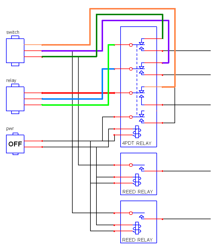
When the Controller is off it is effectively out of the circuit. This is accomplished using NO/NC (Normally Open/Normally Closed) relays and routing the standard circuit thru the NC contacts as below where the red/blue/green lines from the Electro-Steer relays are routed to the orange/purple/dark green lines of the Electro-Steer switch:
When the power is turned on the relays close and the circuit is thru the NO (normally open) contacts as below:
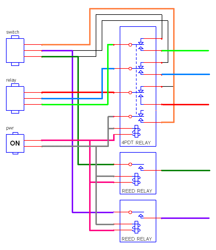
In this configuration the red/blue/green lines from the Electro-Steer relays are routed into the controller for manipulation by other logic, the purple/dark green lines from the Electro-Steer switch are also routed into the controller, and the orange line from the Electro-Steer switch is routed to the gray ground line.
The aforementioned other logic is extremely simple. The bottom two lines from the reed relays feed directly in Moto board digital ports. This allows software to determine the state of the Electro-Steer switch buttons. The upper three lines from the 4pdt relay are switched by a second pair of reed relays that are controlled by another pair of Moto board digital ports. This allows software to control the Electro-Steer relays to turn the trolling motor.
A 'configuration' switch pad is provided, with 4 switches feeding past pull-up resisters to otherwise unused Moto board digital ports. These switches are thus 'soft', meaning that they do nothing other than allow their state to be examined by software. The software in turn associates meaning and action with the switch states. To allow inexpensive and available parts to be be used the pad will accommodate x8, x6, or x4 dip switches, but only the 4 closest to the center of the main pcb are actually used.
A word about power: I built my first PowerTroll with 12v logic but the Acroname Moto board and compasses need 5v. They can take raw 12v by virtue of the regulator on the Moto , but the regulator is small and it get 'very warm' with 12v input and a couple of compasses. With a waterproof case it's hard to dissipate the heat, so 'blazing hot' is a better description, and putting a larger regulator inside that case is not much help. That's why I now use 6v logic and the Radio Shack 6v converter, which basically incorporates a regulator in the 12v plug.
Second Page
The primary purpose of the side pcb is to connect power, serial, and I2C channels from the main pcb to the Moto board. These are direct connections between the three 16 receptacle. connectors. The side pcb also provides for a 2nd serial connector for the Moto serial channel, a serial channel for the FPU, and a mount point for the vertical compass perpendicular to the horizontal compass.
Two types of compass are accommodated in the same set of pcb mounting holes; the pinout differences between these two devices is reconciled by connections on the jumper pad.
Third Page
The third page of the schematic shows the connection and jumpers for the main pcb horizontal compass and for the optional accelerometer (and its associated 3.3 volt voltage regulator) and the optional FPU. The compass jumpers on the main pcb are just like those on the side pcb but select for the device type of the horizontal compass.